 3DP Hub
DXC2 Extruder Guide
Published
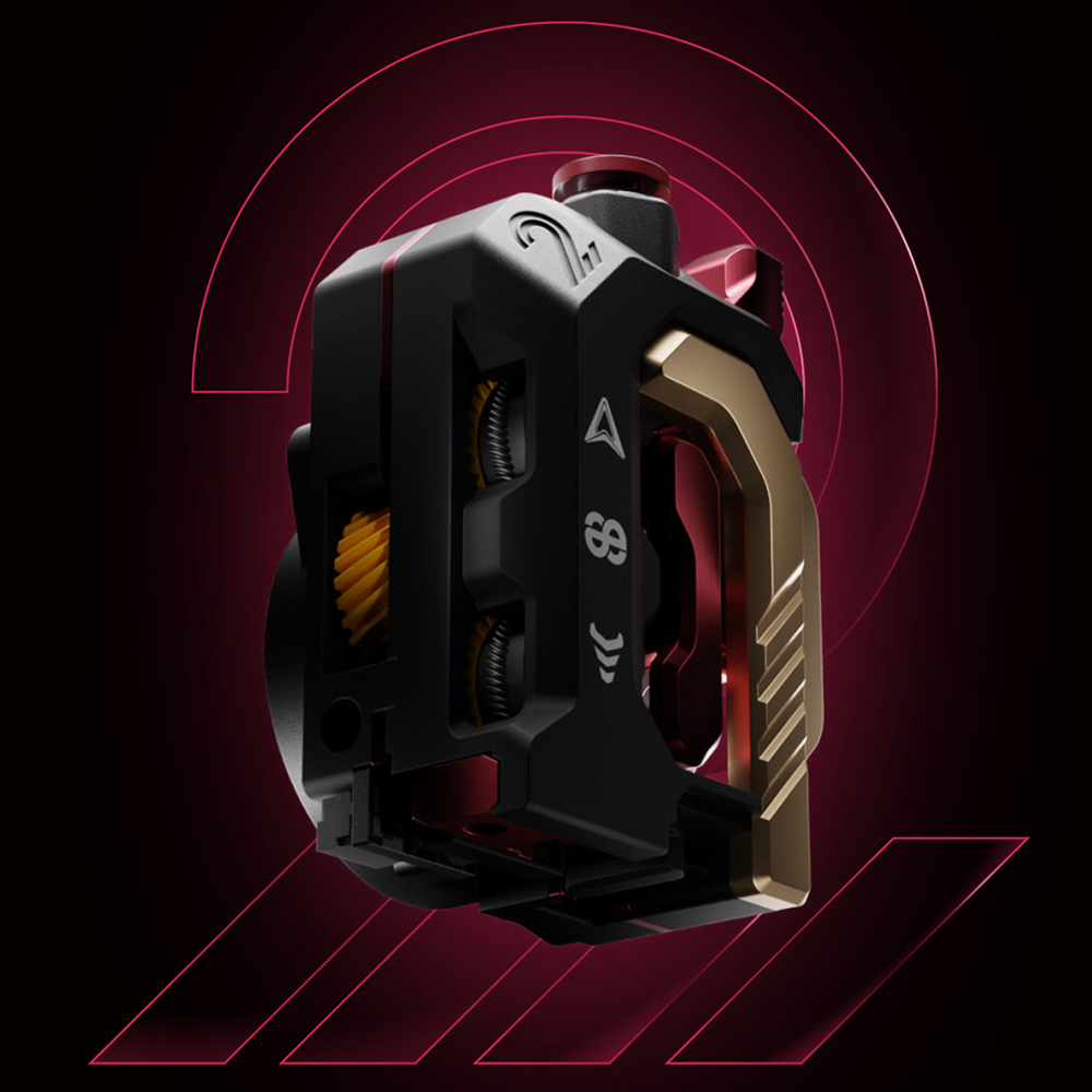
Complete extruder redesign for the Creality K2 series by DevilDesign × Phaetus. Featuring a patented Magnetic Snap quick-release, dual-gear linkage for superior grip, DLC-coated replaceable blades, and real-time filament runout detection.
Search
Unknown module type: video
Configuration guidelines
This project requires you to make config changes. Back up your config and use comments (#) to save the original values.
For example:
retraction_speed: 6 # original was 5
Everything after the # will be ignored by the printer
Bill of materials
Printed parts
Print the riser and cover using ABS, ASA, PC or PA filament to withstand the heat generated by the printer components. The LEOTE Riser is recommended, as the Phaetus riser is less forgiving when it comes to bowden tube routing.
Embed 4x5mm magnets into the riser.
1. Removing the factory extruder
Power off the printer. Open the tool head front cover, press the round cap, and pull out the PTFE tube.
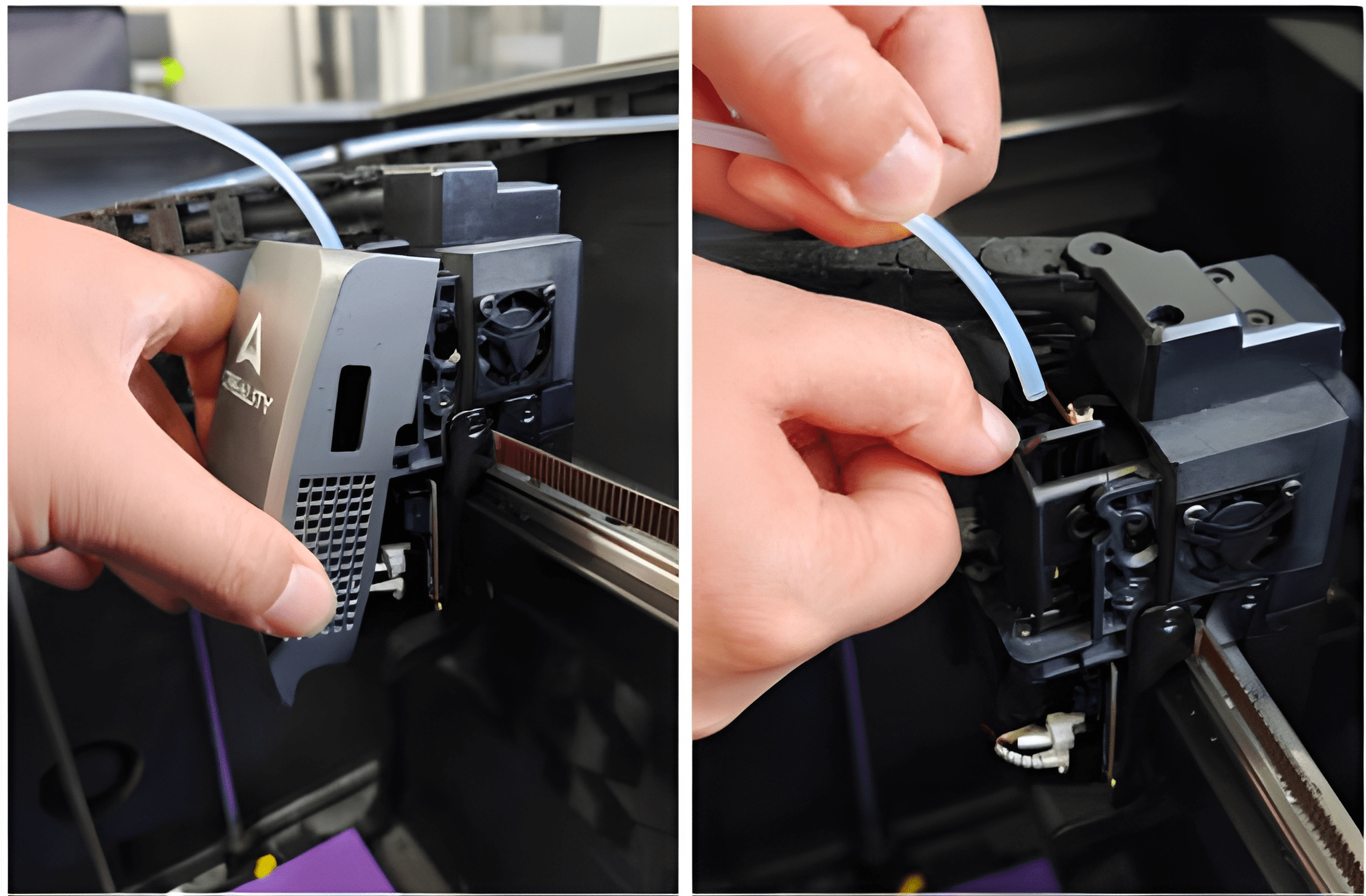
Remove 2 screws on the right side and 1 screw on the left side of the extruder.
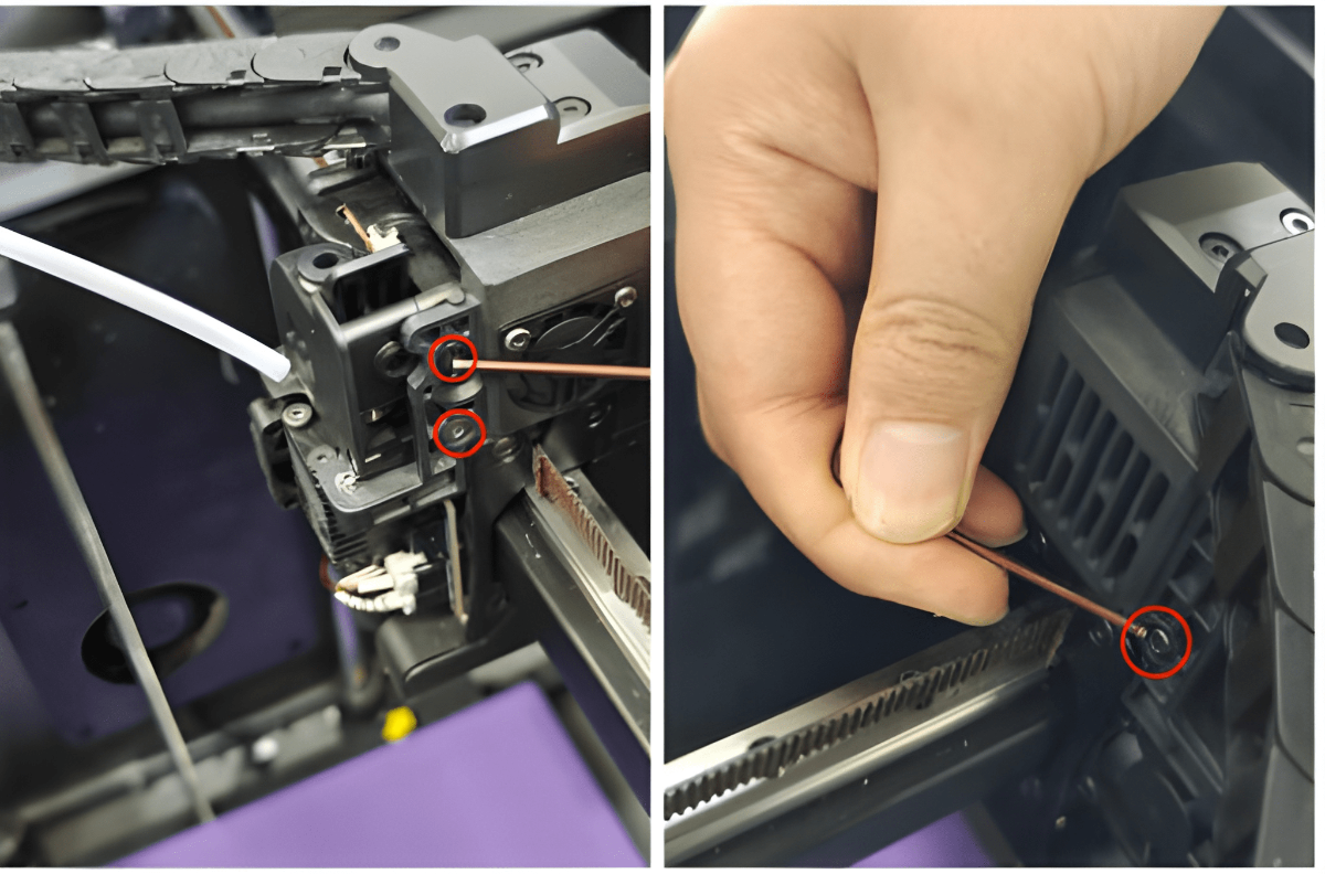
Remove the 2 screws securing the extruder motor. Gently pull the extruder forward to separate it from the motor.
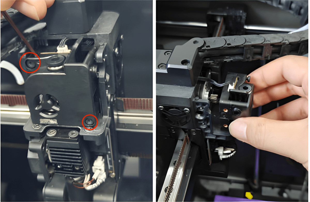
Press the side clips of the connectors and unplug the filament sensor and cutter sensor.
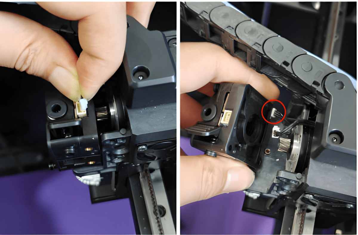
Remove the original extruder.
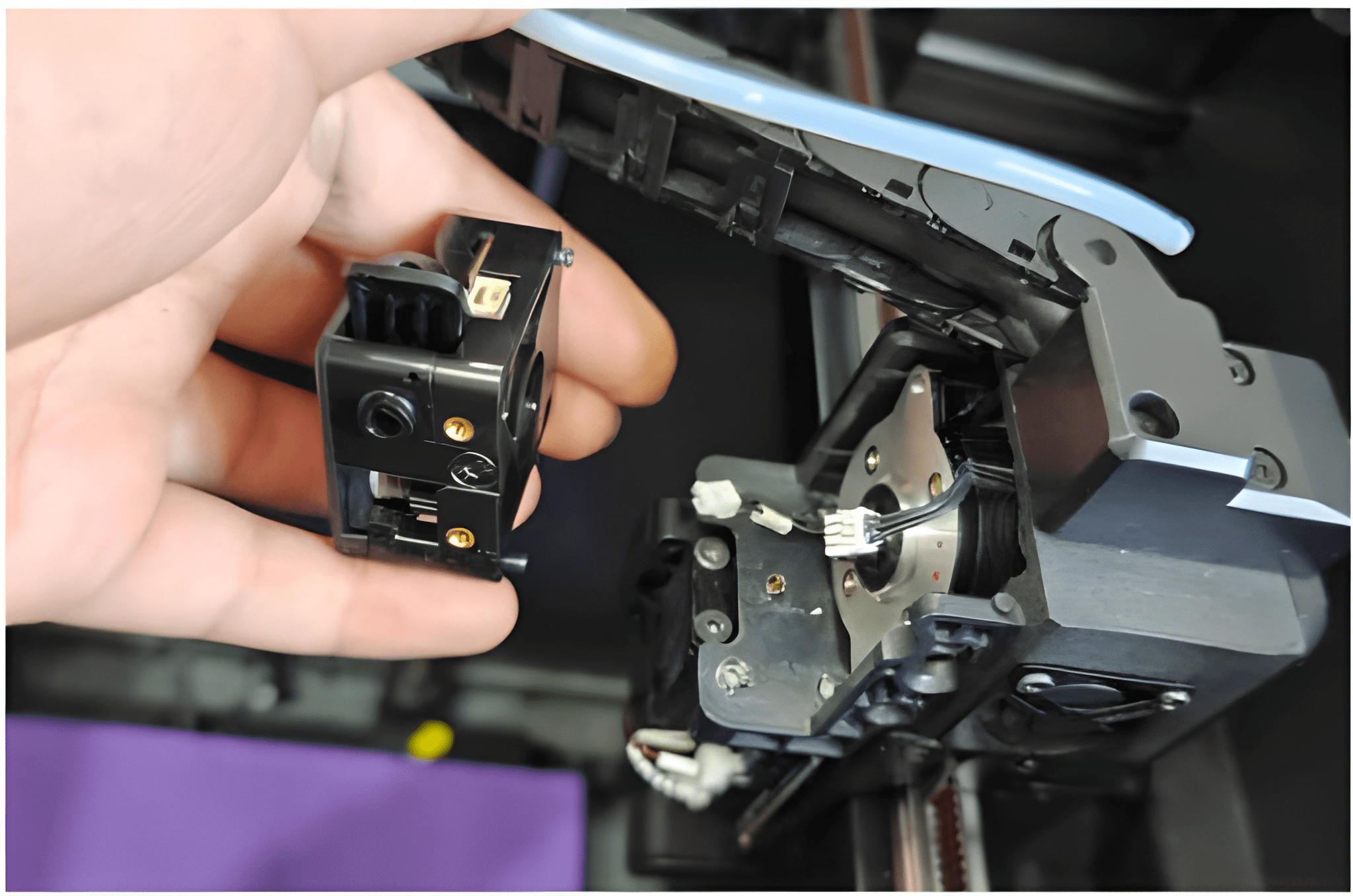
2. Replacing the Cable Chain Mount
Remove the original cable chain mount: Use a wrench to remove the 3 screws securing it. Lift the top cover from both sides and set it aside.
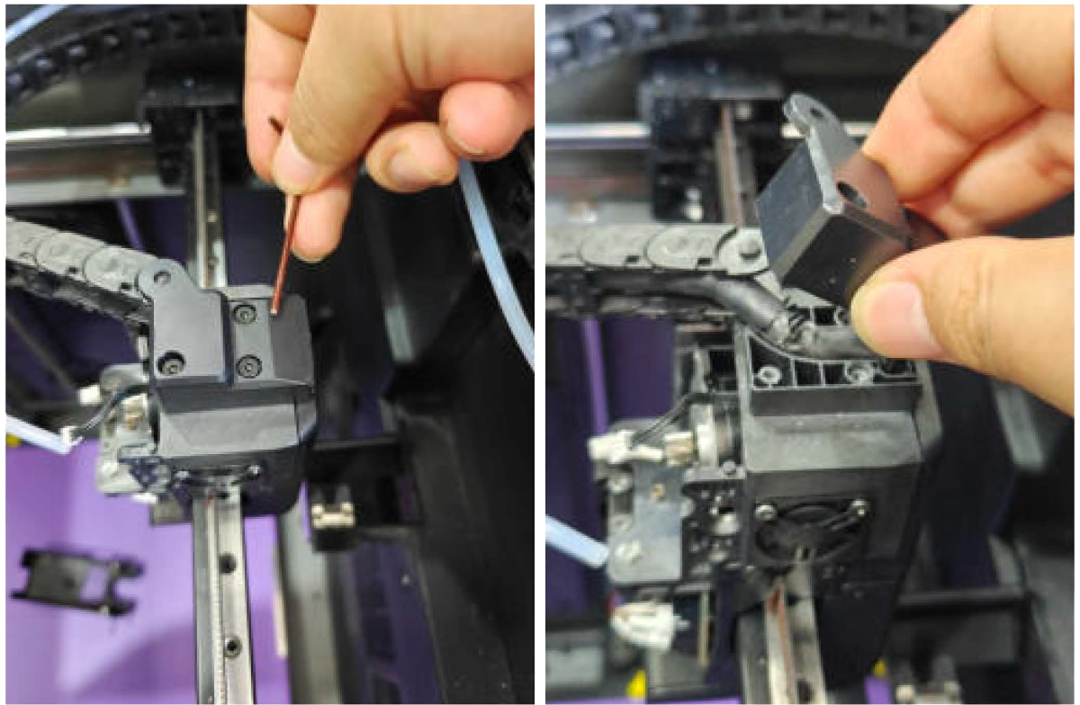
Remove the last link of the cable chain: Insert an H1 .5 hex wrench into the slot, pry upward to release the clip, and remove the last link.
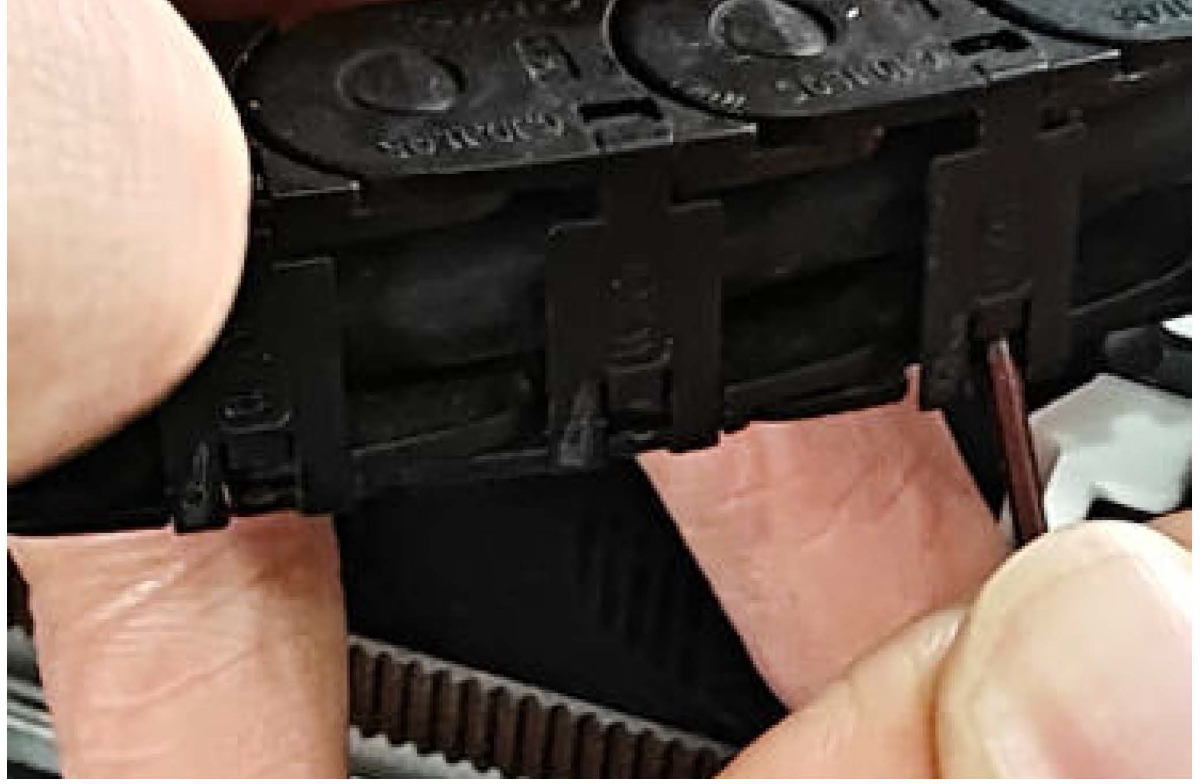
Install the printed riser: Take the cable chain riser printed earlier. Insert the print head cables into the opening of the chain mount as shown in the diagram.
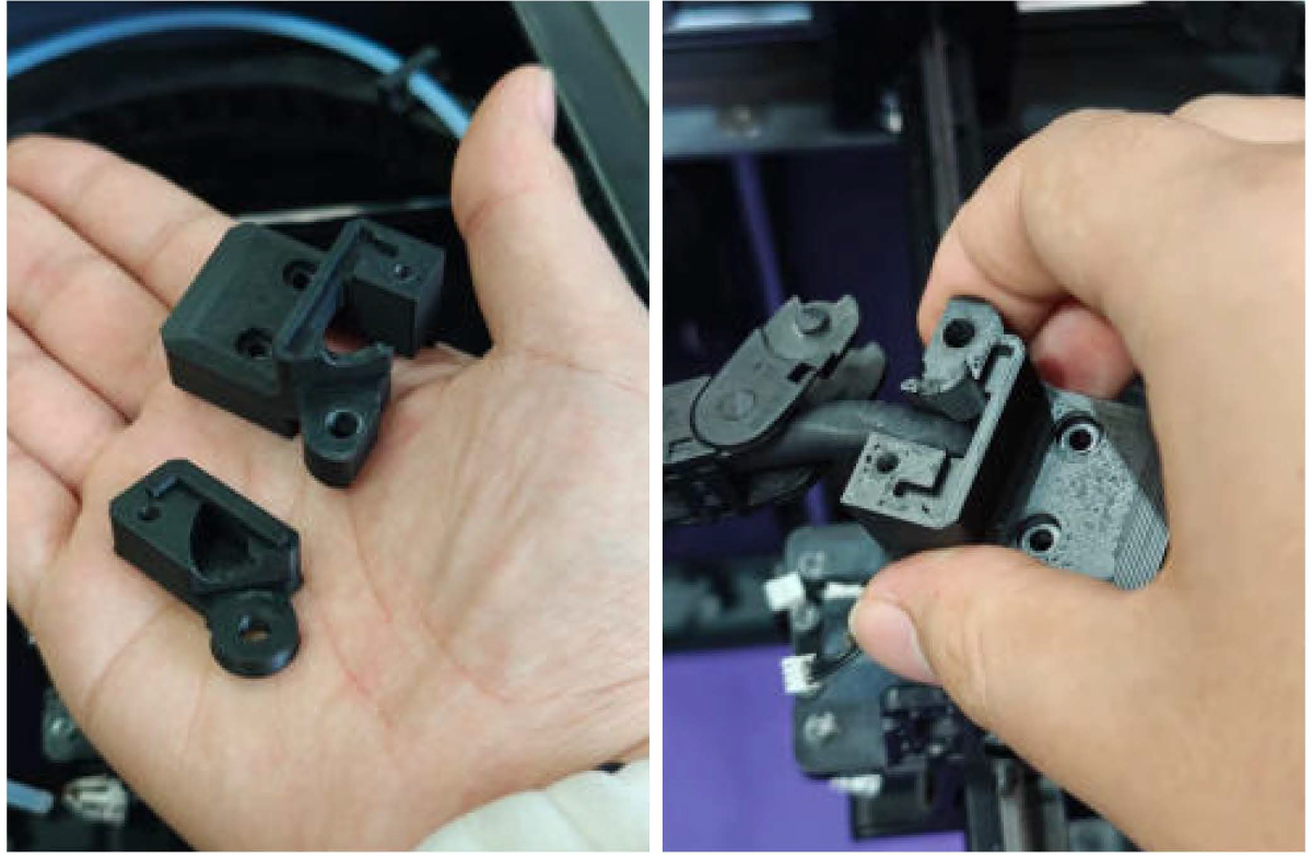
Attach the riser to the print head: Secure it using the 3 original screws saved earlier. Route the cables through the opening and place them into the semicircular cable channel.
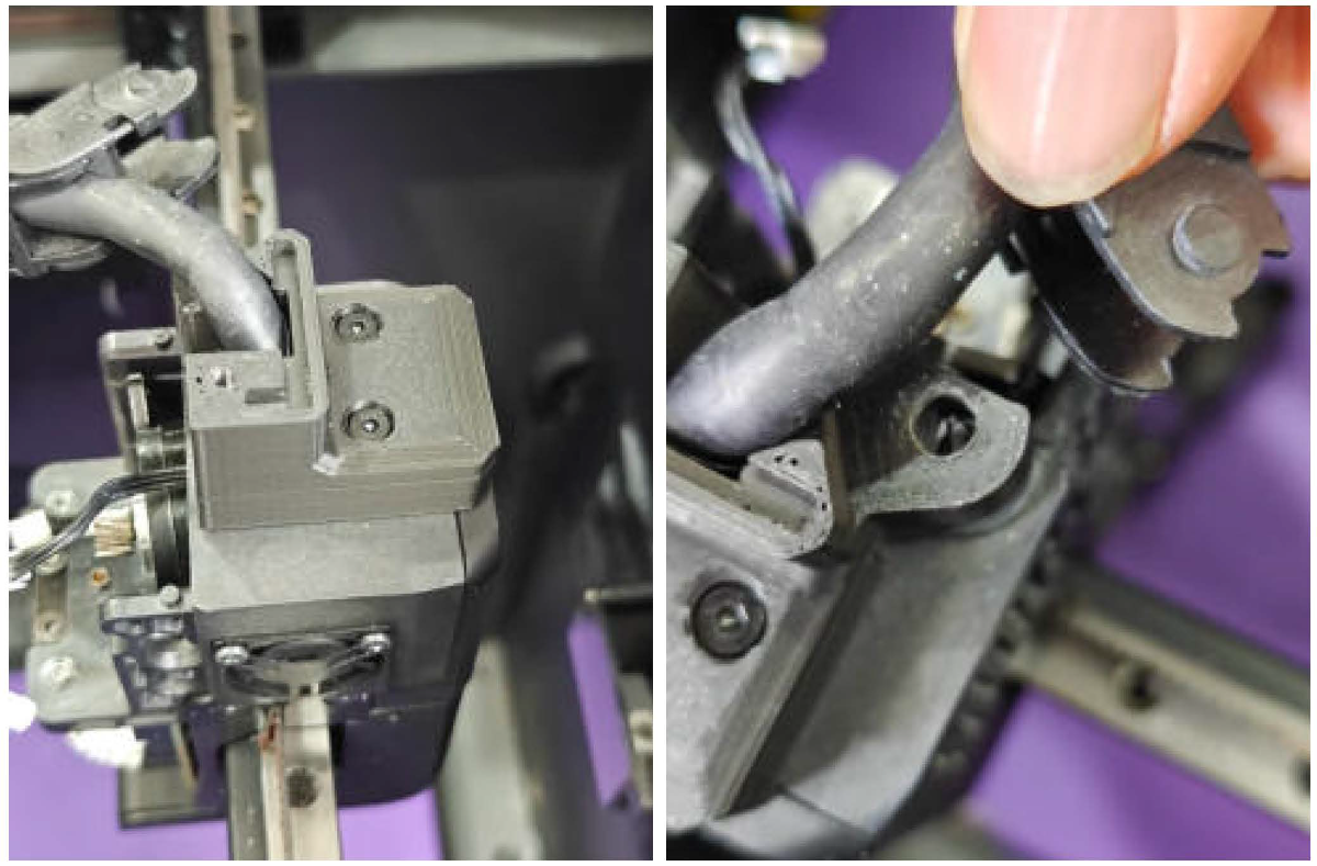
Insert the lower tab of the last chain link into the hole on the chain mount.
Insert the upper tab into the hole on the top cover.
Align the protrusions on the underside of the top cover with the recesses on the mount.
Secure the left side with 1 remaining original riser screw.
Secure the right side with 1 M3x15 self-tapping screw (included in the accessory kit).
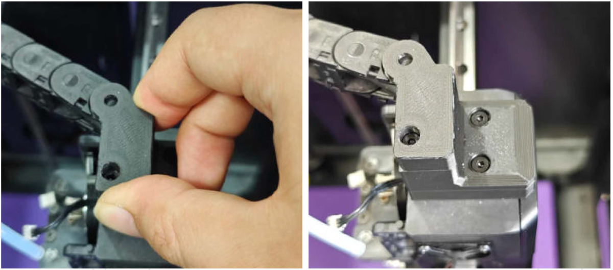
3. Installing the DXC2 Extruder
Take the original extruder you removed earlier. Use a wrench to unscrew the side screws and separate the front and rear covers.
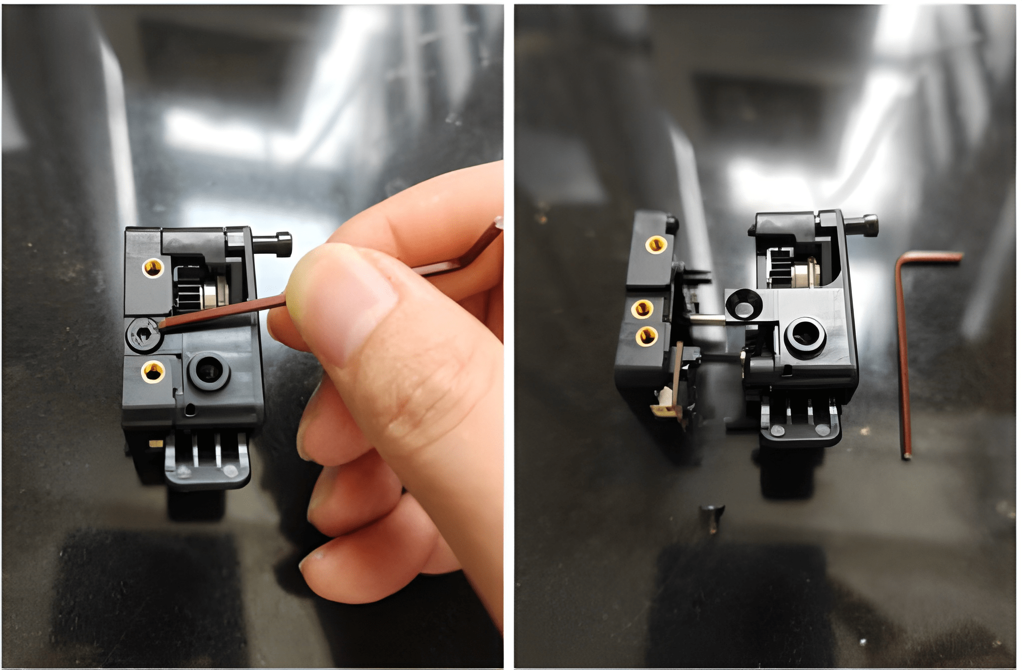
Remove the 3 screws securing the sensor PCB on the rear cover.
Detach the cutter sensor and filament runout sensor.
Reassemble the remaining parts of the original extruder and store them properly.
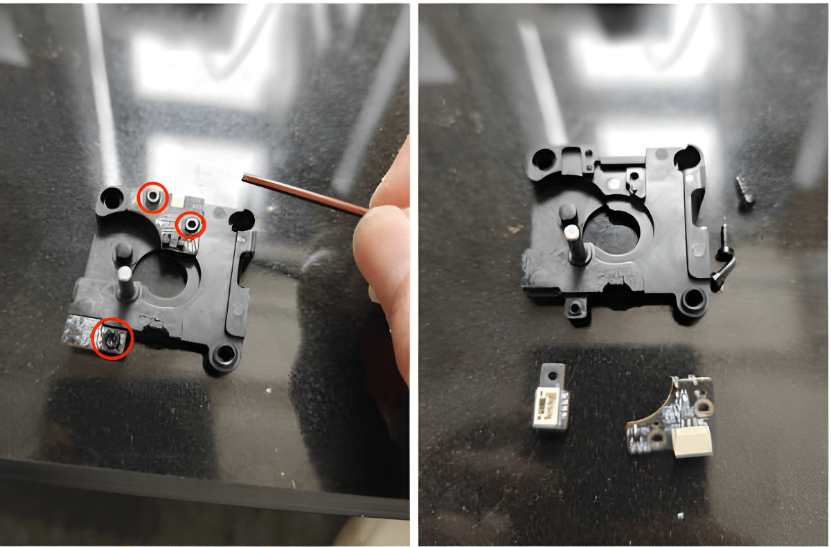
Take out the DXC2 extruder and the 2 original sensor PCBs. Prepare 3 M2x4 self-tapping screws from the accessory kit.
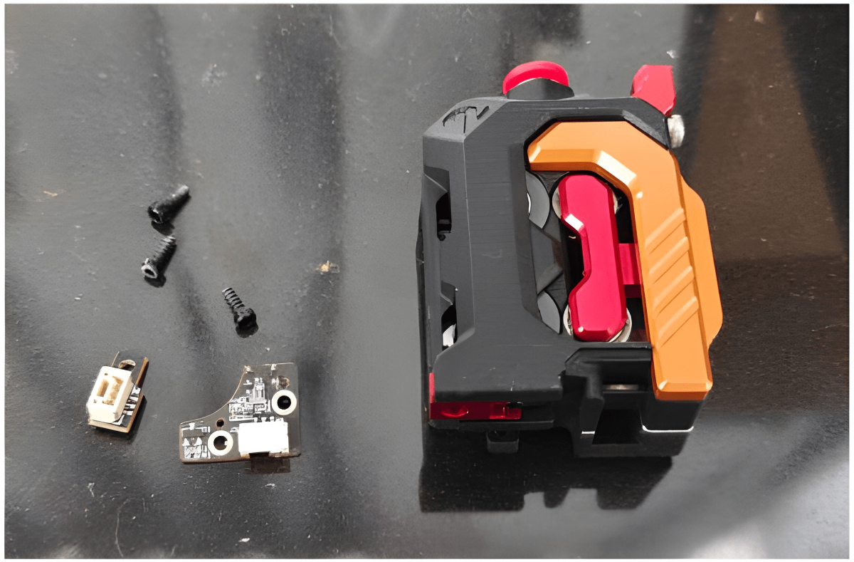
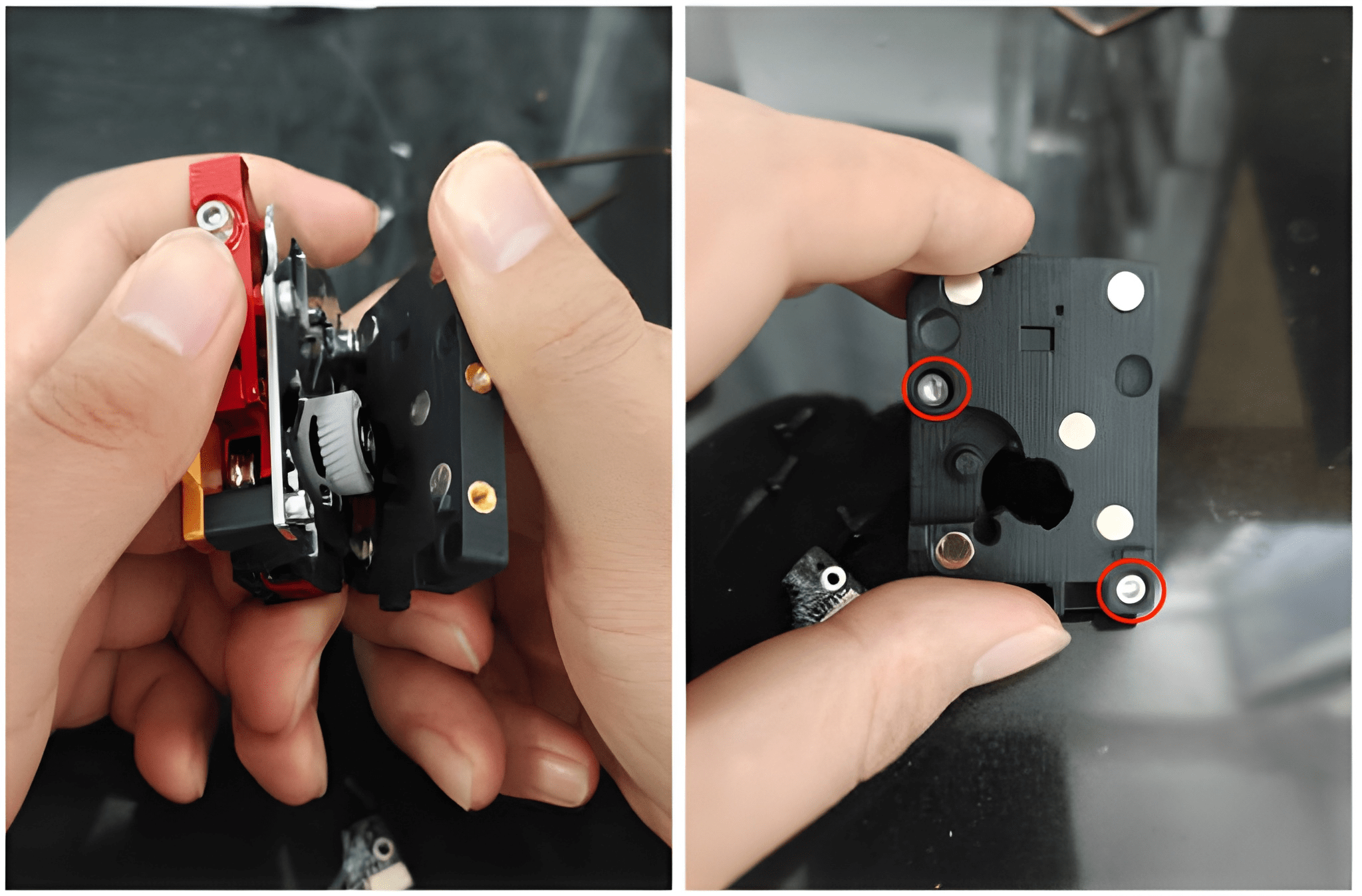
Carefully snap open the DXC2 extruder to separate the front cover assembly from the rear cover.
Remove the motor screws from the rear cover and set them aside temporarily.
lnstall the filament runout sensor and cutter sensor
Ensure the cutter sensor sits flush against the extruder body with no gap. Secure both sensors using the 3 M2x4 self-tapping screws.
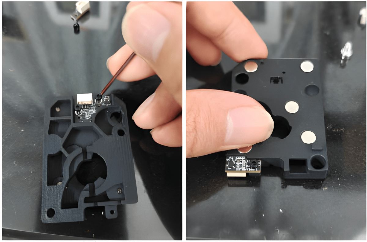
Plug in the cutter sensor connector.
Use the motor screws set aside earlier to mount the motor onto the rear cover.
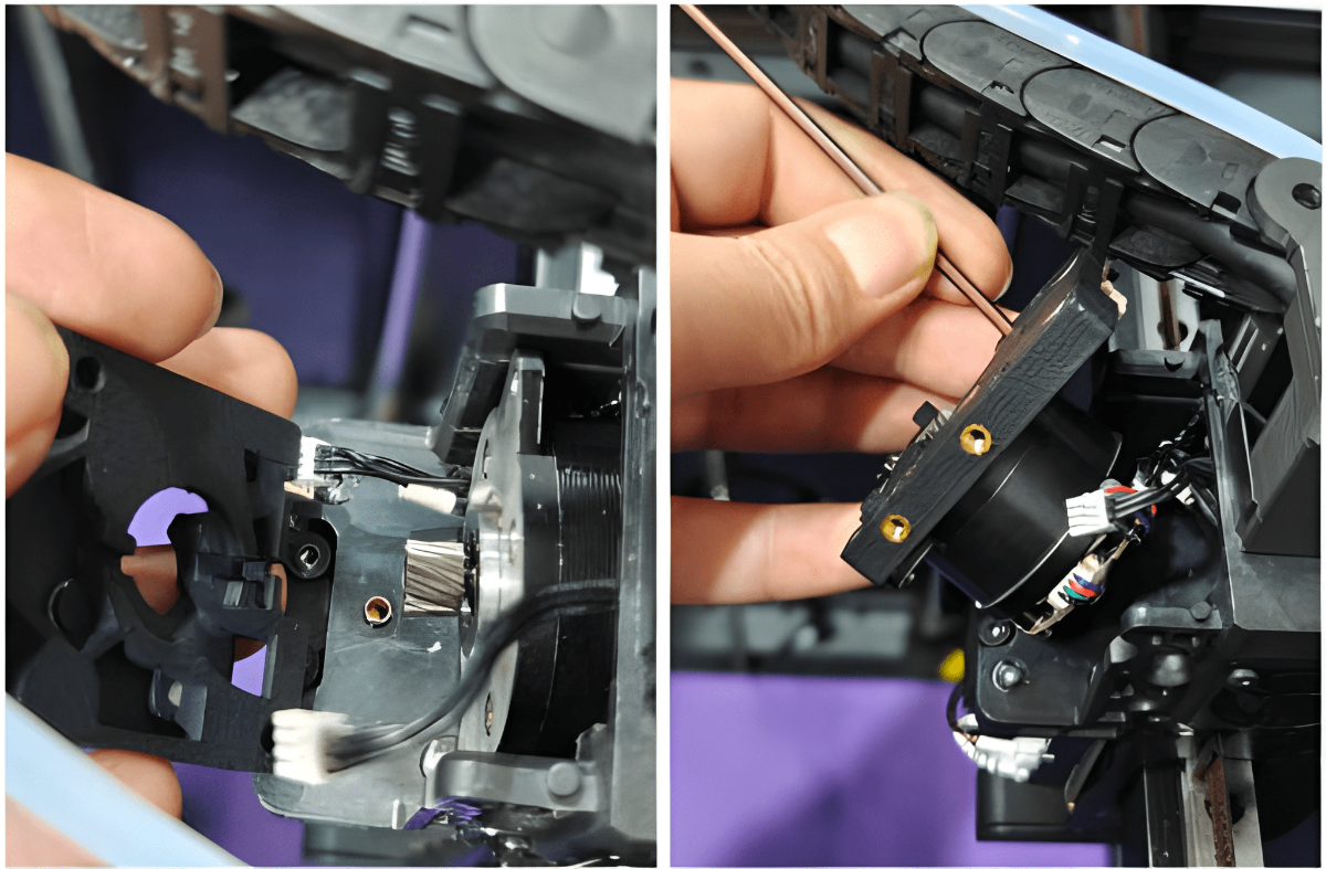
Plug the filament runout sensor connector into the sensor.
Align the rear cover with the extruder mounting position - ensure the 3 screw holes on both sides line up.
Take out the 3 original extruder mounting screws.
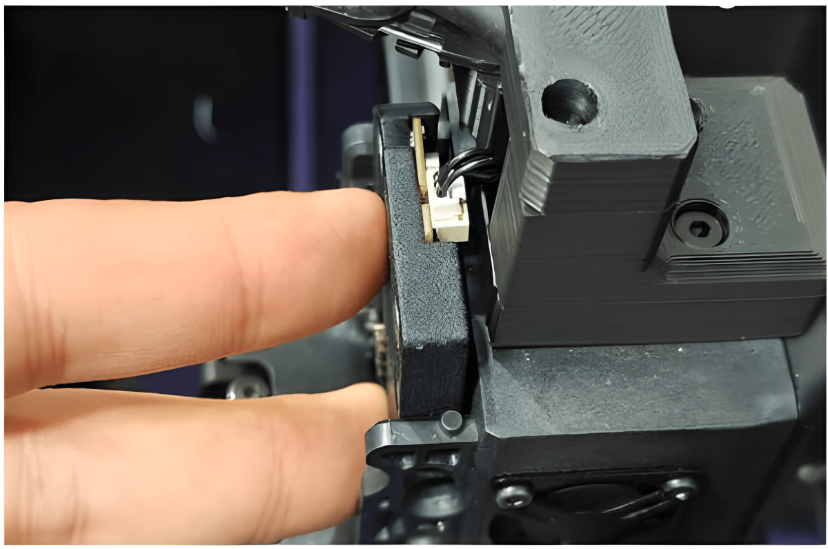
Partially tighten the 3 screws first, then fully tighten them once alignment is confirmed.
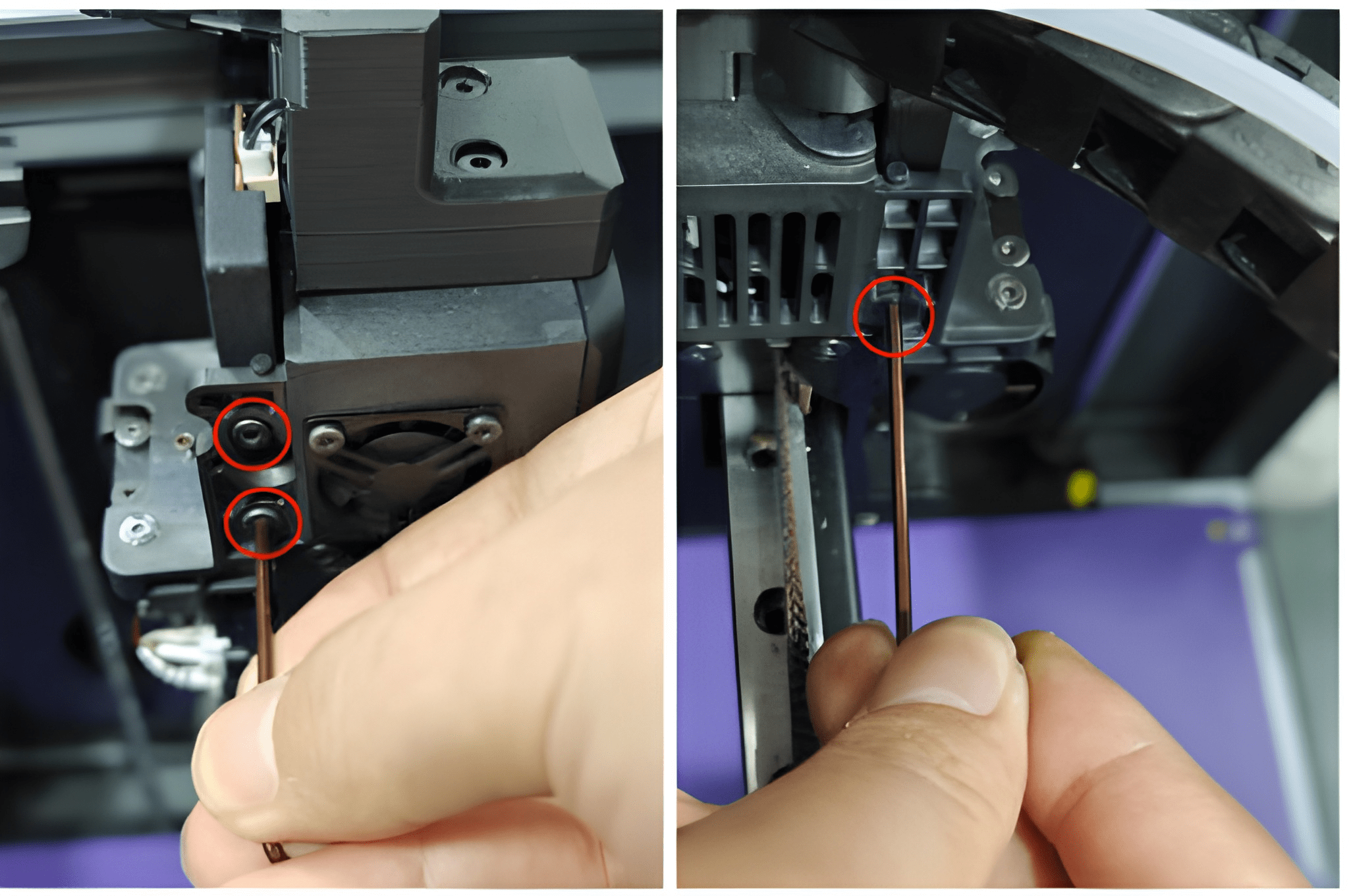
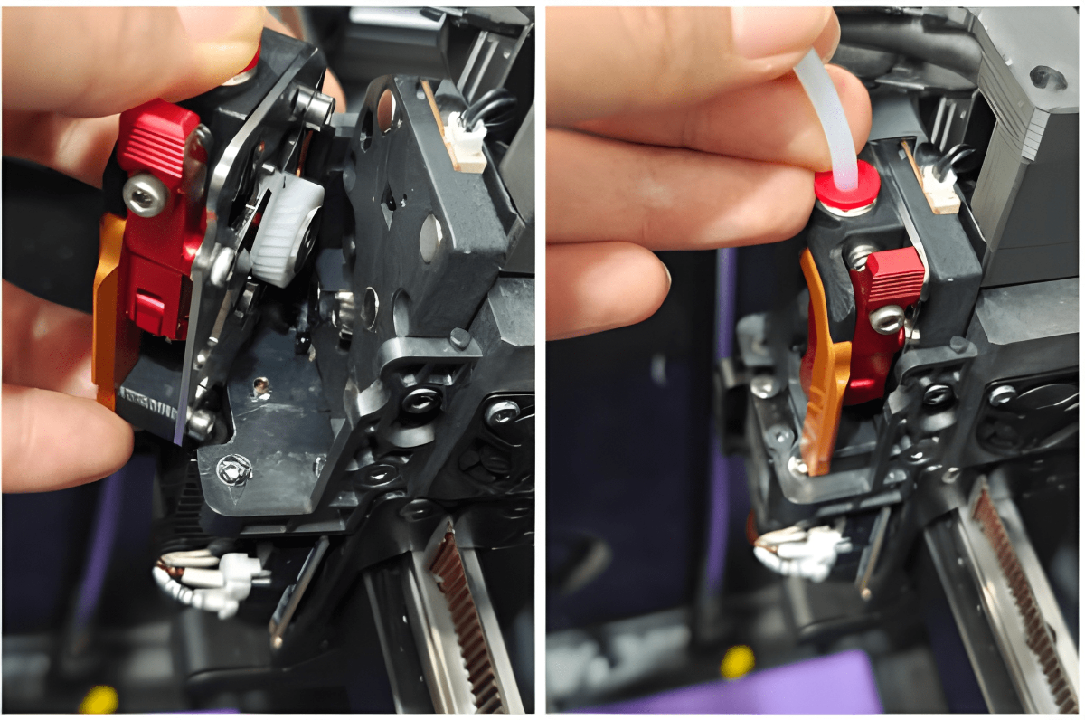
Align the front cover assembly with the rear cover and snap them together - no visible gap should remain.
Reinsert the PTFE tube.
4. Firmware Modification
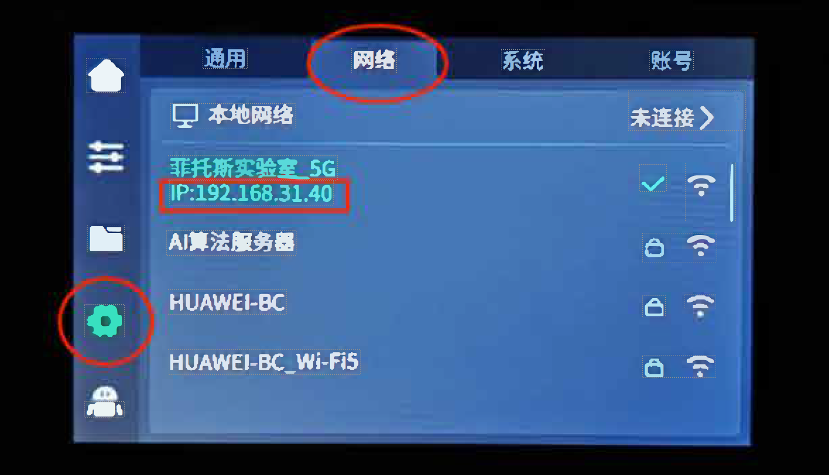
On your printer, go to the network settings page and note the IP address (e.g., 192.168.31.40).
Connect your computer to the same network, open a browser, and enter:
IP:4408 (e.g., 192.168.31.40:4408) - this opens fluidd, where you can make config changes.
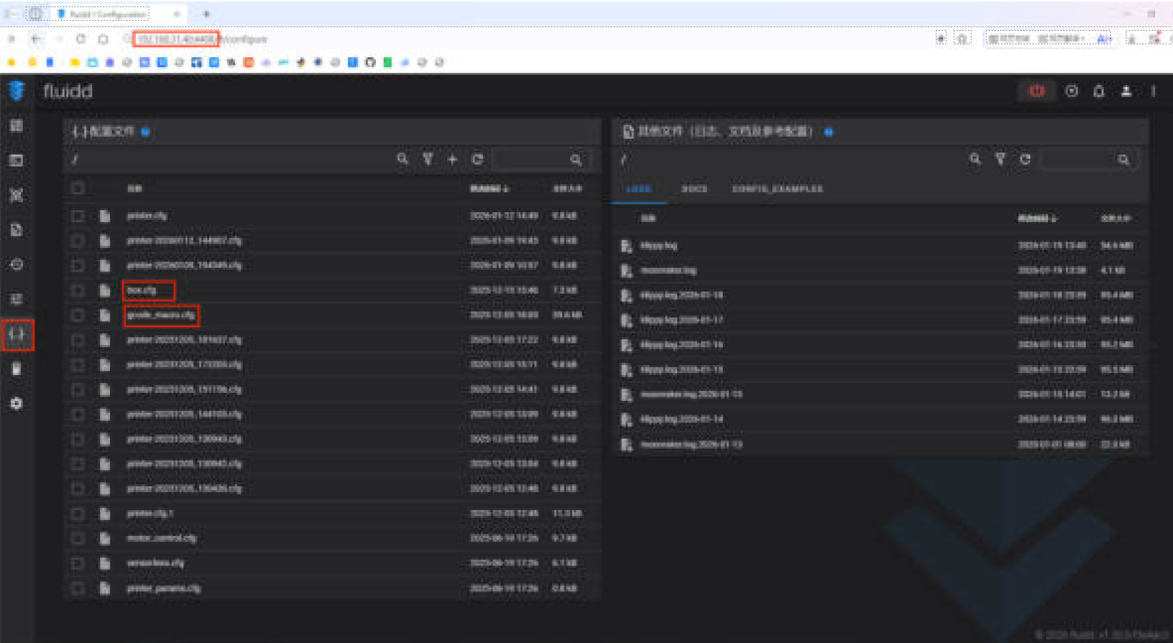
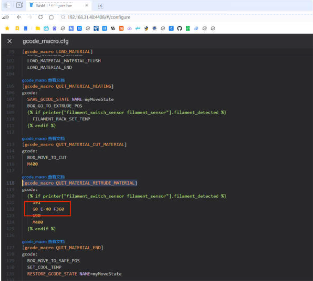
Go to the Configuration interface, find and open the gcode_macro.cfg file.
Locate [gcode_macro QUIT_MATERIAL_RETRUDE_MATERIAL] and change the retraction value to E-40 (as shown below).
Click Save but don't restart yet.
Find and open the box.cfg file.
Locate [box] and modify Tn_retrude to -20.
Final: Tn_retrude: -20
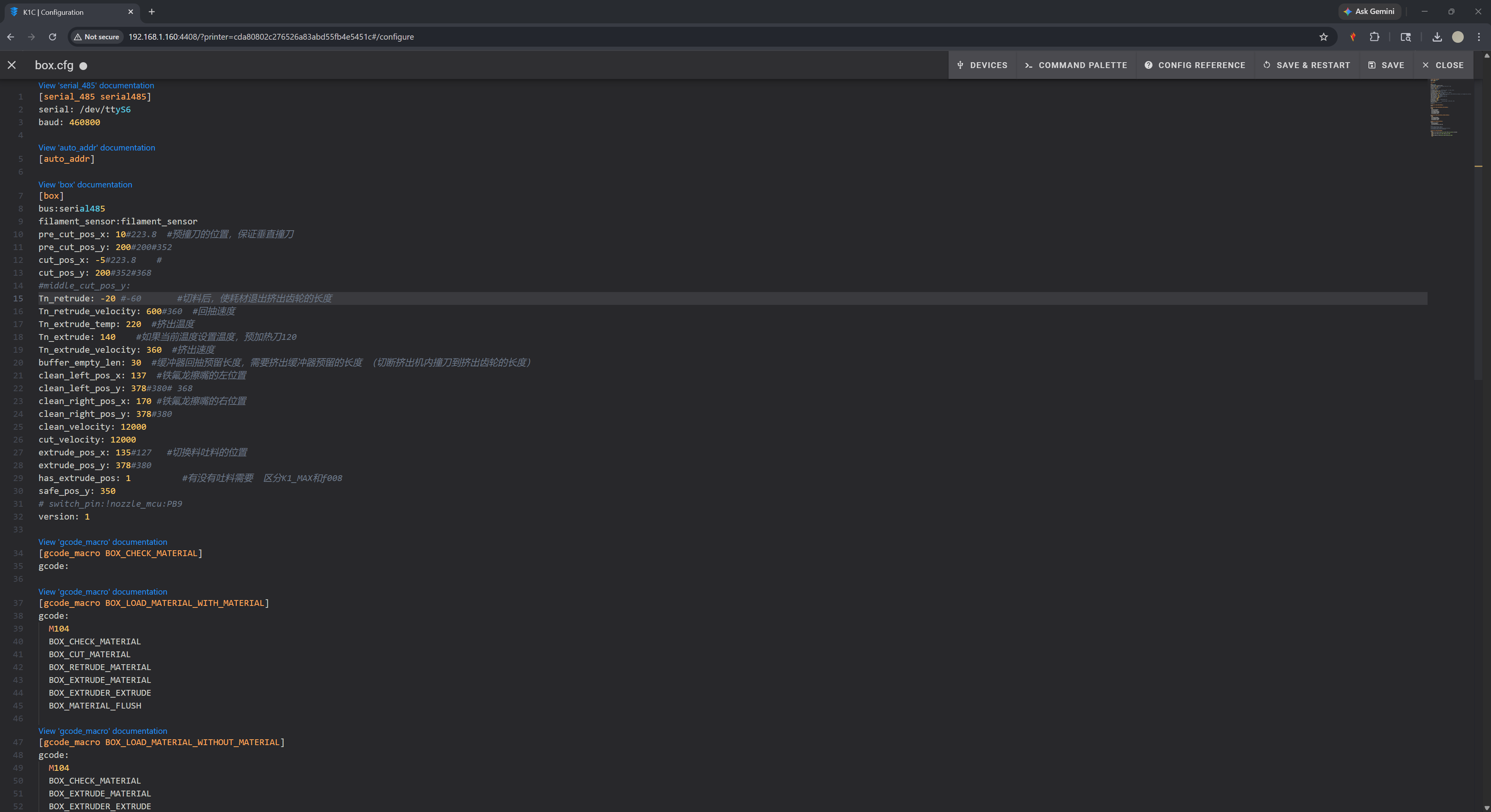
Now click save and restart to apply the changes
5. Tension Adjustment
One of the benefits of upgrading to the DXC2 is the adaptive pressure rocker arm. This varies how much the gears grip on the filament. When switching between TPU and hard filaments, you can dial in the adaptive pressure range by adjusting the screw on the top-right of the extruder.
Gently pull on the filament while adjusting the screw until you can no longer pull it out, or until you feel adequate resistance in the case of TPU.
6. Troubleshooting
Symptom | Causes | Troubleshooting Steps |
|---|---|---|
Not extruding | Not enough grip, dirty gears, wet filament | Dial in the tension, clean the gears, dry the filament. |
Tooth marks on filament | Too much grip, clogged hotend | Dial back the tension, clean out hotend, dial in filament settings |