 3DP Hub
DXC Extruder Guide
Published
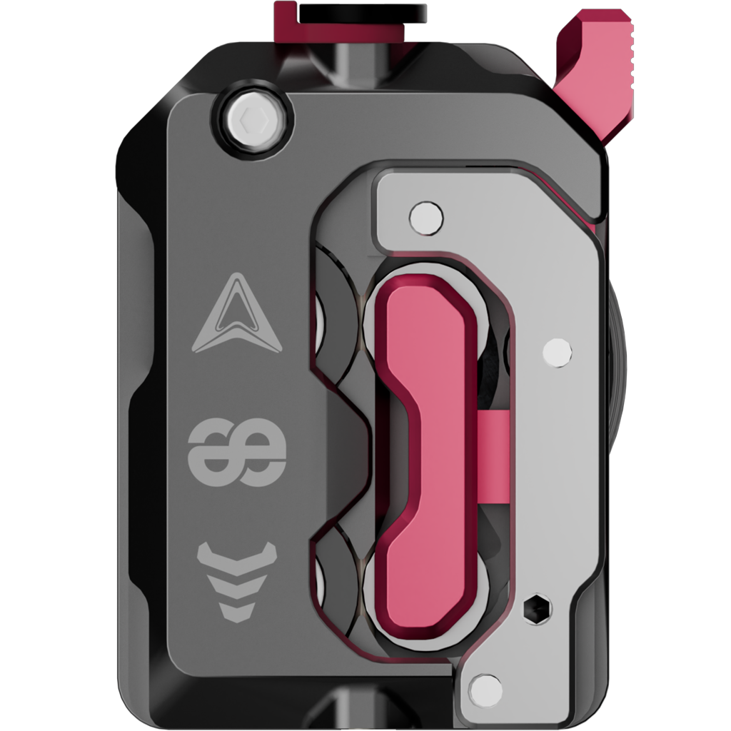
The DXC Extruder is a dual‑gear direct‑drive upgrade that delivers smooth, reliable filament feeding for higher-quality 3D prints across multiple materials. It is the best drop-in upgrade for the Creality K1 series. Root access is required to ensure your config is set up correctly.
Search
Configuration guidelines
The DXC is marketed as a drop-in, root-free upgrade, though its compatibility varies by firmware. However, since the hardware geometry differs from the factory extruder, standard retraction G-code may cause sub-optimal performance or clogging.
For the best results, it is recommended to gain root access and manually update the printer.cfg file and retraction macros.
Read the links below for more information.
Bill of materials
| Qty | Item | Links | |
|---|---|---|---|
| 1 | DXC Extruder |
| Qty | Item | Links | |
|---|---|---|---|
| 1 | Heatsink |
Printed parts
A lid riser and cable tuck clip are recommended to ensure clearance. Print out of ASA, ABS or better.
If your printer isn't working, or you simply want top-quality prints or CNC machined parts, you can order using the link below.1. Introduction
A collaboration between D3vil Design, Phaetus, Runice and Creality, the DXC extruder upgrade eliminates the issues inherent to the stock K1 series extruder, and brings new benefits on top of the reliability.
The adaptive pressure allows for softer filaments such as TPU to feed correctly for stable extrusion and smooth feeding without getting squished and clogging.
It’s coated to handle abrasives like wood, glass and carbon fiber, the dual helical gears reduce filament grinding by 60% and double the contact area to reduce slippage.
The built in Omron filament sensor will correctly detect runouts, and allows for the often problematic factory filament sensor to be removed - reducing the resistance in the filament path, and eliminating random stoppages and complete misses which can be devastating with overnight or multi-day prints.
The DXC extruder upgrade was designed to use the factory motor and be a seamless, cost effective swap no matter your skill level. You don't need any tools which didn't already come with your printer, you don't need to print any parts out of ABS, you don't need to gain root access and mess around with configuration files, you don't need to buy a new motor, and you don't need to assemble it.
With that being said, this is an in depth guide which covers all grounds - including lost screws, optional steps for different firmwares, dealing with stripped motor threads, cable management, macro optimization, pulling the extruder apart for maintenance and more.
Everything is broken down step by step, starting from the very basics of retracting the filament and lowering the bed, so even if this is your very first day with your printer, you will be able to successfully upgrade it and learn along the way. Let's get started!
2. Lower the bed
On the printer screen, tap the second button on the side bar.
Tap on the Movement/Temp. Tab at the top.
Tap on the Home Z button on the right, and wait for it to return to the home position.
Tap on the 30mm button to set the movement steps to 30mm.
Tap on the Z↓ button 3 times to lower the bed half way. This will give you more room to work on the printer.
3. Retract the filament
Tap on the Extrude/Retract tab.
Select the printing temperature of your current filament (230c for PLA).
Press the Retract button and wait for the process to finish.
Shut down the printer by pressing the power switch at the back.
Remove the extruder cover by prying gently.
Switch the extruder to the unlocked position.
Remove the locking tab from the extruder.
Remove the bowden tube while pressing down on the push lock connector.
4. Remove the LIDAR module
If you have a Lidar module or side mounted probe upgrade, you may have to remove it in order to gain access to one of the screws securing the toolhead cover.
(Optional) Mark the top side of the lidar cable (or probe) so you can easily identify the correct orientation when you reinstall it.
Remove the lidar cable from the left side of the toolhead.
Remove the two M3x4 countersunk screws which secure the lidar bracket to the top of the lidar module using a 2mm allen key or hex driver.
Remove the two M3x4 countersunk screws which secure the side of the lidar module bracket to the left side of the carriage using a 2mm allen key or hex driver.
5. Remove the toolhead cover
Removing the toolhead cover will give you access to connect the filament sensor later on, and the option to remove the extruder motor if you want to assemble the extruder outside of the machine.
Remove the single M3x4 ultra low socket head cap screw which secures the left side of the toolhead cover to the carriage using a 2mm allen key or hex driver.
Remove the single M3x4 ultra low socket head cap screw which secures the right side of the toolhead cover to the carriage using a 2mm allen key or hex driver.
Mark the top side of the part cooler fan cable so you can remember which way goes up when you reinstall it later.
Remove the part cooler fan cable from the front of the toolhead PCB.
6. Free the toolhead PCB
Freeing the toolhead board will give you more space to work with. You do not have to completely remove it but gaining some wiggle room makes it a lot easier to connect the wiring as it’s a tight fit.
Remove the two M3x18 button head cap screws securing the top of the toolhead PCB to the carriage using a 2.5mm allen key or hex driver.
Remove the single M3x20 button head cap screw securing the bottom of the toolhead PCB to the carriage using a 2.5mm allen key or hex driver.
7. Remove the extruder housing
Remove the extruder motor cable from the right hand side of the toolhead PCB.
Remove the beauty cover by prying gently
Remove the two M3x6 socket head cap screws which secure the extruder housing to the right side of the carriage using a 2.5mm allen key or hex driver.
Remove the single M3x6 socket head cap screw which secures the extruder housing to the left side of the carriage using a 2.5mm allen key or hex driver.
8. Separate the motor
Remove the two M3x14 button head cap screws securing the motor to the extruder housing using a 2.5mm allen key or hex driver.
9. Option 1: Use the supplied screws
Attach the extension cable to the extruder motor. This is necessary because the motor will be oriented with the extruder motor cable facing the LiDAR side - opposite to the factory configuration.
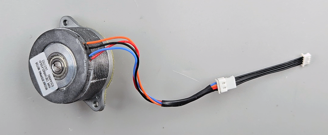
Use the supplied M3x20 and M3x9 button head cap screws to secure the motor to the extruder housing with a 2mm allen key or hex driver.
10. Option 2: Use longer screws
If your motor threads are stripped, you'll want to use longer screws and nuts. The housing needs to be separated in order to swap out the lower screw.
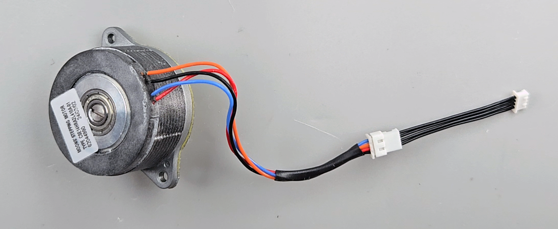
Attach the extension cable to the extruder motor. This is necessary because the motor will be oriented with the extruder motor cable facing the LiDAR side - opposite to the factory configuration.
Remove the single M3x16 socket head cap screw which secures the lower-rear of the extruder housing using a 2mm allen key or hex driver.
Remove the single M3x16 socket head cap screw which secures the center-rear of the extruder housing using a 2mm allen key or hex driver. (This has a larger head and only has threads at the end)
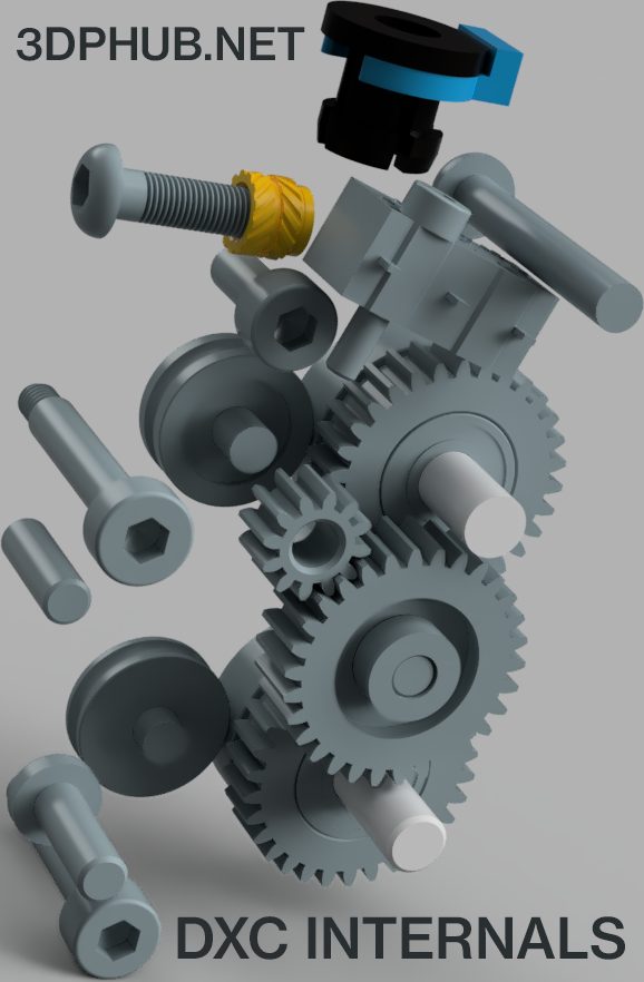
Carefully separate the housing to expose and swap the lower M3x20 button head cap screw for an M3x25 button head cap screw. Do it over a tray to ensure you don’t lose any components. Refer to this image if something falls out.
Reassemble the extruder housing. Torque the M3x16 screws down evenly by alternating between them, tightening by a few turns each time, using a 2mm allen key or hex driver.
Swap the M3x9 button head cap screw which secures the motor to the top of the extruder housing for an M3x14 button head cap screw using a 2mm allen key or hex driver.
Tighten the M3x25 and M3x14 button head cap screws to secure the motor to the extruder housing with M3 nuts and washers using a 2mm allen key or hex driver. Ensure the filament sensor wires are sitting in their channel and not squished.
11. Optional: Install the heatsink
This will help to prevent heat creep and overheating.
Add a thermal pad or thermal compound like boron nitride to the top of the extruder motor.
Attach the heatsink to the top of the extruder motor, tilted slightly away from the lidar side to avoid damaging the wires.
12. Optional: Install the cable tuck clip
Option 1 (Lazy): Use two 2x8mm socket head cap screws to secure the cable tuck clip to the rear of the carriage with a 1.5mm allen key or hex driver. These can be threaded directly into the clip.
Option 2: (Best): Use two 2x10mm socket head cap screws and two M2 nuts to secure the cable tuck clip to the rear of the carriage. This is more reliable.
Route the cables neatly behind the clip.
13. Optional: Reinstall the toolhead PCB
If you removed the toolhead PCB, you can now reinstall it.
Use the two M3x18 button head cap screws to secure the top of the toolhead PCB to the carriage using a 2.5mm allen key or hex driver.
Use the single M3x20 button head cap screw to secure the bottom of the toolhead PCB to the carriage using a 2.5mm allen key or hex driver.
14. Install the new extruder
Use the original M3x6 socket head cap screw to secure the DXC extruder to the left side of the carriage using a 2.5mm allen key or hex driver.
Use the supplied M3x4 socket head cap screw to secure the DXC extruder to the top of the right side of the carriage using a 2.5mm allen key or hex driver.
Use the original M3x6 socket head cap screw to secure the DXC extruder to the bottom of the right side of the carriage using a 2.5mm allen key or hex driver.
Torque all three screws down evenly by alternating between them, tightening by a few turns each time, using a 2.5mm allen key or hex driver.
With the partially exposed side of the connector oriented toward you (red cable on top), connect the filament sensor to the topmost port on the right side of the toolhead PCB.
With the partially exposed side of the connector oriented toward you, connect the extruder cable to the middle port on the right side of the toolhead PCB.
15. Reinstall the lidar module
If you have a lidar module or upgraded probe, you can now reinstall it.
Use the two M3x4 countersunk screws to secure the side of the lidar module bracket to the left side of the carriage using a 2mm allen key or hex driver.
Use the two M3x4 countersunk screws to secure the lidar bracket to the top of the lidar module using a 2mm allen key or hex driver.
Reattach the lidar cable to the left side of the toolhead. Ensure the side you marked is on top
16. Optional: Filament sensor config
The filament sensor should be plug and play depending on your firmware, but to guarantee optimal functionality, you can manually update the config. You’ll need root access to make these changes.
Optional: Back up printer.cfg and gcode_macro.cfg
Optional: If you want to disable the factory filament sensor, remove or comment out the [filament_switch_sensor filament_sensor_1] section in printer.cfg.
Copy the following section and paste it into printer.cfg. This tells the printer that it has the DXC filament sensor connected to the filament port on the toolhead PCB, and tells it what to do when it runs out.
[filament_switch_sensor DXC]

pause_on_runout: true

switch_pin: !nozzle_mcu:PA10 # sensor port on the toolhead board

event_delay: 1.5

pause_delay: 0.25

insert_gcode:

  M118 Filament inserted

  LOAD_MATERIAL # LOAD_FILAMENT IN SIMPLEAF

runout_gcode:

  M118 Out of filament

  {% if printer.extruder.can_extrude|lower == 'true' %}

    G91

    G1 E-30 F180 # retract 30mm slow

    G1 E-50 F2000 # retract  50mm fast

    G90

  {% endif %}
17. Optional: Add a respond section
If there is no [respond] section in printer.cfg, add it to prevent feedback errors.
[respond]

default_type: echo

default_prefix: 18. Optional: Improve the factory retraction gcode
This code is optimized for the DXC extruder, and will work better than using the factory code. You’ll need root access to make these changes. Refer to the root access guide if you need help.
Copy the following macros and paste them over the relevant sections in your gcode_macro.cfg file
[gcode_macro LOAD_MATERIAL] # LOAD_FILAMENT IN SIMPLEAF
gcode:
  LOAD_MATERIAL_CLOSE_FAN2
  M109 S{printer.custom_macro.default_extruder_temp}
  G91
  G1 E110 F300 # ORIGINALLY E80 F180, CHANGED FOR DXC
  LOAD_MATERIAL_RESTORE_FAN2
[gcode_macro QUIT_MATERIAL] # QUIT_FILAMENT IN SIMPLEAF
gcode:
  SAVE_GCODE_STATE NAME=myMoveState
  RESTORE_E_CURRENT
  M109 S{printer.custom_macro.default_extruder_temp}
  M83
  G1 E20 F300
  G1 E-15 F3000
  G1 E-22.4700 F2400
  G1 E-6.4200 F1200
  G1 E-3.2100 F720
  G1 E5.0000 F356
  G1 E-5.0000 F384
  G1 E5.0000 F412
  G1 E-5.0000 F440
  G1 E5.0000 F467
  G1 E-5.0000 F495
  G1 E5.0000 F523
  G1 E-5.0000 F3000
  G1 E-35 F3000
  SET_E_MIN_CURRENT
  RESTORE_GCODE_STATE NAME=myMoveState
19. Optional: SimpleAF retraction tweak
The goal is simple: You're following the gcode flow for when the filament runs out, and adding a few mm of retraction.
Open printer.cfg and find out which macro is called on runout by the [filament_switch_sensor filament_sensor]
Example: runout_gcode: _ON_FILAMENT_RUNOUTFrom here you have two options: You can either add the factory macro (experimental) and call that instead (replace _ON_FILAMENT_RUNOUT) or follow the gcode flow further and tweak the SimpleAF gcode
Follow the flow of the _ON_FILAMENT_RUNOUT macro and look for retraction lines (G1 E.........) or a macro
20. Optional: Disable Arc Fitting
This will improve the response time of the filament runout detection.
Navigate to the Quality tab in your slicers Process section.
Scroll down to the Precision section.
Uncheck Arc fitting.
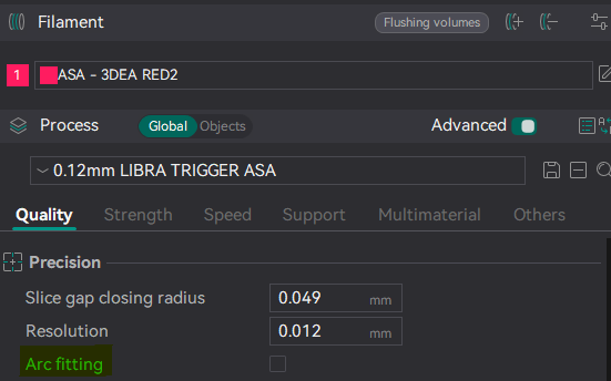
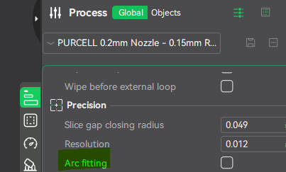
21. Optional: Revert extruder config
This is required if you are converting to the DXC from the Libra, Cyclops, Trigger or any other extruder which uses a 10 tooth motor. This does not apply for the factory 12 tooth motor.
Find your printer MCU version at the top of printer.cfg
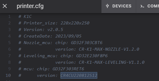
Refer to the example config for your printer version for default values
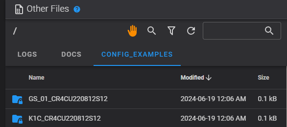
Revert the dir_pin value to default in the [extruder] section of printer.cfg.
Revert the rotation_distance to default in the [extruder] section of printer.cfg.
Revert the run_current to default in the [tmc2209 extruder] section of printer.cfg.
22. Optional: Adjust clearance
If you do not use a riser or if you use a heatsink you may need to adjust your config to account for the larger dimensions.
Home the printer.
Babystep the toolhead toward the rear until it nearly hits the back.
Note the Y position in Fluidd.
Find the [stepper_y] section in printer.cfg.
Change the position_max value to a safe value
23. Prime the extruder
Feed the filament into the top of the extruder while squeezing the red tensioner arm inward or tightening the screw on the right side.
Gently pull on the filament while loosening the screw until it has a good grip.
Insert the bowden tube to the extruder while pressing down on the push lock connector.
Insert the red locking tab to secure the bowden tube to the extruder.
On the printer screen, tap on the Extrude/Retract tab.
Select the printing temperature of your current filament (230c for PLA).
Press the Extrude button and wait for the process to finish.
Clean up the mess and the nozzle
24. Optional: Calibrations
It is best practice to perform calibrations after installing an upgrade.
25. Optional: Sensor toggle

26. Optional: Tension adjustment
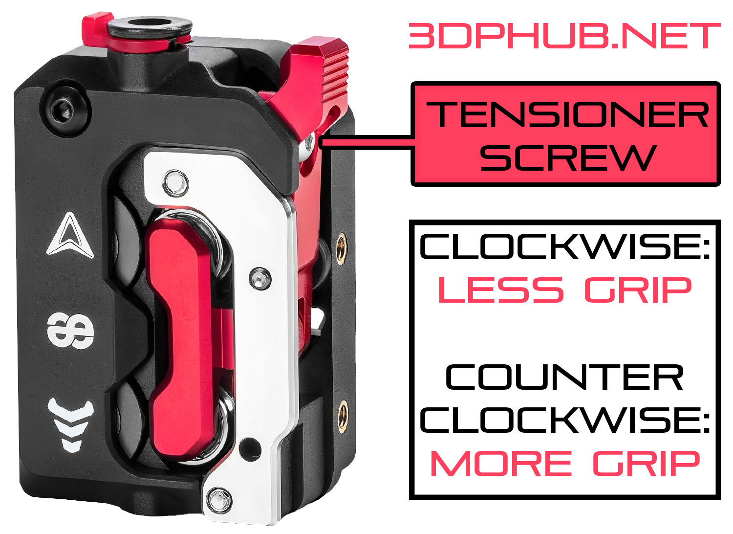
You may need to manually adjust the tension when switching between hard and soft filaments by turning the screw on the right side of the tensioner.
This allows you to dial in the perfect grip for different filaments to prevent slipping or squishing.
The tensioner design is BACKWARD compared to most extruders: Turning the screw clockwise (tightening it) reduces the tension. Backing the screw out increases tension. Gently pull on the filament while adjusting the screw until you can no longer pull it out, or until you feel adequate resistance in the case of TPU.
27. Optional: Secure the tension screw
This is not an extruder issue - this is a gantry issue and should be addressed at the source.
A cheap and easy workaround is to use Loctite 243 or RTV silicone to secure the screw, but again - you should address the vibrations of the printer.
28. Additional information
FILAMENT SENSOR BALL SIZE: 4MM DIAMETER (You can find them inside a 608 bearing)